Racepak Wiring Diagram Help
Https Documents Holley Com Techlibrary Sportsman Manual Pdf

Racepak Help Tips

Racepak Universal Efi Interface Module Fueltech Usa

Pin En Ignitions And Electrical

Top 10 Best Honda Engine Swaps Honda Civic Honda Civic Engine Honda Vtec

Pin By Terry Connarn On 1972 914 1 7l Data Logger Digital Alarm Clock Logger

Connect pc to vsd sportsman unit with serial cable 9 pin on one end and stereo end on the other.
Racepak wiring diagram help. Backing up your racepak data logs. Racepak llc was founded in 1985 by spencer eisenbarth and ron armstrong originally as racepak and its parent company competition systems incorporated csi. Racepak v300 wiring diagram 04 01 2019 04 01 2019 5 comments on racepak v300 wiring diagram racepak help tips click on one of these titles. Using v300sd clutch input as tbevent.
Adding to the cleanliness and simplicity of gabe s work is racepak s exclusive single cable v net technology where you simply daisy chain their sensor wiring together using the blue v net connectors. Variety of racepak iq3 wiring diagram. Msd 7761 pulse count passed to rp. How to measure for the ds collar.
Dan richard fishing recommended for you. The v net approach to wiring not only contributes to the weight savings we ve seen with the rewiring of the car it s also very clever in. It reveals the parts of the circuit as streamlined shapes as well as the power and also signal links in between the devices. It can be used with any racepak vnet capable data logger such as the g2x g2xpro and v300sd for use as a dash board display.
250 ds iq3 display dash installation manual 5 introduction racepak part number 250 ds iq3 is an iq3 display only dash. Setting the chart colors changing font sizes racepak users sometimes want to change the size of the print that appears on their screen. It does not have a built in data logger gps or accelerometers as does the iq3ld model. Both men were engineers with strong backgrounds in electrical and mechanical applications and both had an interest in motor sports.
How to get an average of one data channel. Benefits of the racepak v net system. Generally racepak will set this to display from 5 seconds before the start of the run 0 500 to 1 0 or 2 0 seconds beyond the typical elapsed time recorded by a car such as your car. A wiring diagram is a simplified standard photographic representation of an electric circuit.

Tech Deep Dive Getting To Know Msd S Power Grid Features

Elite Ecu Haltech Iq3 Smartwire Official Haltech Forums

Racepak Data Systems Manualzz

Factory Five Forums Abs Brake System

Racepak Smart Wire Comparison To The Norm Youtube

Motorsports Ecu Wiring Harness Construction With Images Ecu Harness Toyota Fj40

Sponsored Ebay Racepak Udxrp Ultradash Extreme Replay 10 Minute Memory Real Time Display With Images Performance Racing Ebay Things To Sell
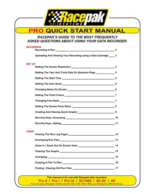
Sc1000 Pro I Ii Series Quick Start Manual Racepak Data Systems

Racepak Iq3 Display Dash Harness Modern Racing

Racepak Iq3 Drag Dash Install Youtube
Racepak Basic Bracket Setup Youtube

Racepak V300sd V500sd Harness Quarter Max

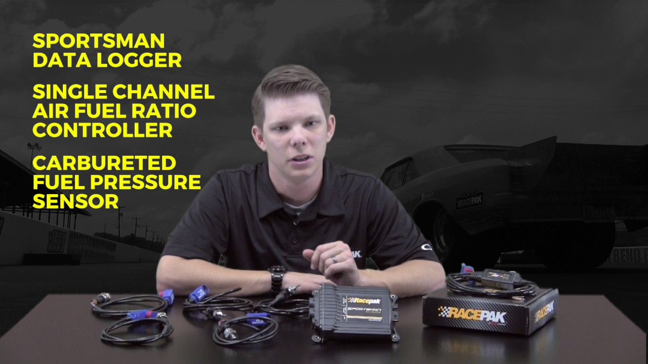
Racepak 4 Channel Air Fuel Controller Hyperaktive Performance Solutions
