R And Rc Firing Circuit Diagram

R R C Firing Circuits Disadvantages Circuit Electronic
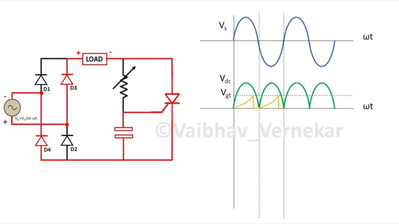
Rc Firing Circuit For Thyristor Scr Full Wave And Graphs Youtube

Pin On Circuit Diagram

Simplest Quadcopter Drone Circuit With Images Electronic

Triac Firing Angle Control Circuit With Images Circuit Angles

Wireless Power Transfer Circuit With Images Mobile Battery
Thyristor circuit showing additional gate.
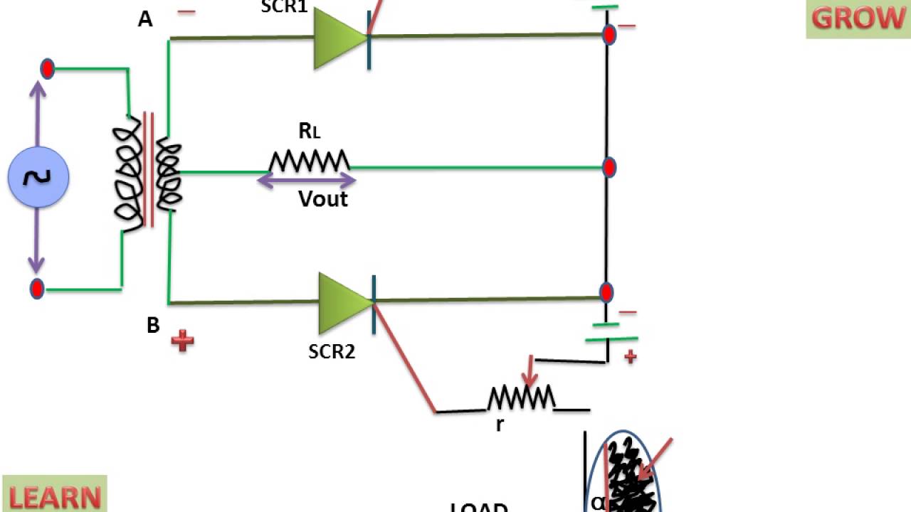
R and rc firing circuit diagram. Controlled hwr and fwr using rc triggering circuit 4. Rc firing circuit for thyristor scr full wave and graphs. Resistance capacitance rc firing circuit. Limitation of the firing angle range of r firing circuit is eliminated by introducing a capacitor and a diode.
The rc circuit resistor capacitor circuit will consist of a capacitor and a resistor connected either in series or parallel to a voltage or current source these types of circuits are also called as rc filters or rc networks since they are most commonly used in filtering applications. Generation of firing signals for thyristors triacs using digital circuit microprocessor. To study operation of r and rc firing circuit for scr. Scr turn off circuits using i lc circuit ii auxiliary commutation.
R firing circuits is simple but suffer from limited firing circuits. In this video i have explained rc triggering circuit of scr with following outlines. Firing angle is limited between 0o to 90o. By changing the phase and amplitude of the gate current a large variation of firing angle is obtained using this circuit.
Thus r c firing circuits can increase the firing angle. Thyristor circuit design primer circuit operation triggering firing circuit design overvoltage crowbar triac circuits when designing a thyristor scr circuit special attention needs to be paid to the trigger circuit. Thyristor rc firing circuit half wave with step by step. R firing circuits is simple but suffer from limited firing circuits.
Ac voltage controller using triac diac combination. Types of rc triggering of scr 3. Resistance trigger circuits are the simplest most economical method. Gate triggering is the most commonly used turn on method employed to switch on the thyristors.
An rc circuit can be used to make some crude filters like low pass high pass and band pass filters. In actual practice firing angle can be varied between 3 o to 90 o. Circuit of rc. Triggering circuits is also called firing circuits.
The limitation of resistance firing circuit can be overcome by the rc triggering circuit which provides the firing angle control from 0 to 180 degrees. During the positive half cycle of the input voltage scr become forward biased but it will not conduct until its gate current exceeds gate threshold. Rc triggering of scr 1. There are various firing circuits available.
Basics of rc triggering of scr 2. Firing angle is limited between 0 o to 90 o. Phasor diagram duration.

Simple Strip Led Lamp Circuit Diagram With Images Circuit

Thyristor Circuit And Thyristor Switching Circuits


An Example Of Transformer Overload And Short Circuit Protection
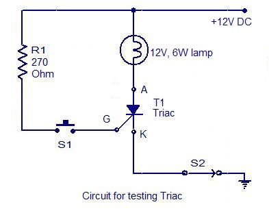
How To Test An Scr
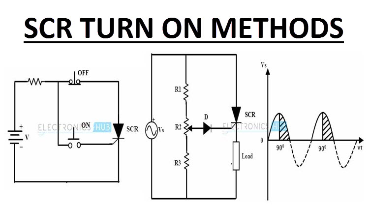
Scr Turn On Methods Scr Triggering Voltage Temperature
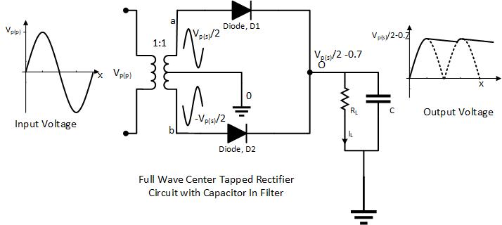
Center Tapped Full Wave Rectifier With Capacitor Filter

Pin On Arduino Diy

Predator Generator Wiring Diagram On Predator Download Wirning

Wiring For 1948 To 49 Ford Trucks 1948 Ford Truck Ford Trucks Ford

Building A Yagi Antenna For Uhf J Tech Engineering Ltd Diy

Pdf 270 Mini Electronics Project With Circuit Diagram

Fm Am X2f Mw And Sw Antenna Amplifier Circuit Diagram Ham
