Kickspace Heater Wiring Diagram
Quiet One Kickspace Install Manual Manualzz

Myson Kickspace 500 Operating Instructions Manualzz
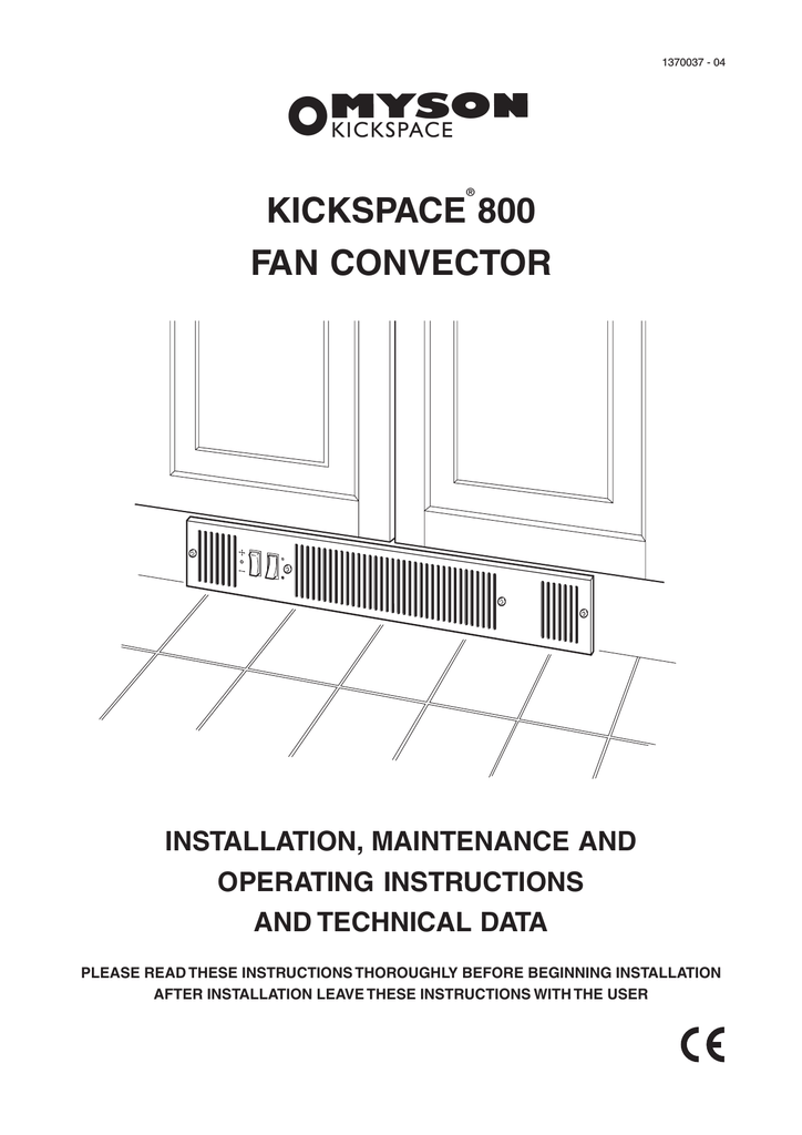
Myson Kickspace 800 Operating Instructions Manualzz

Beacon Morris K84 Twin Flo Iii Kick Space Heater Masterbuilder

Adding A Toekick To A Baseboard Hydronic System Doityourself Com
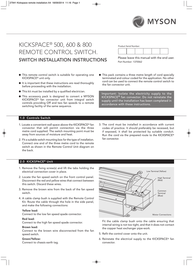
Kickspace Remote Switch Installation Instructions Manualzz

Br brown bl blue bk black r red y yellow g y green yellow.
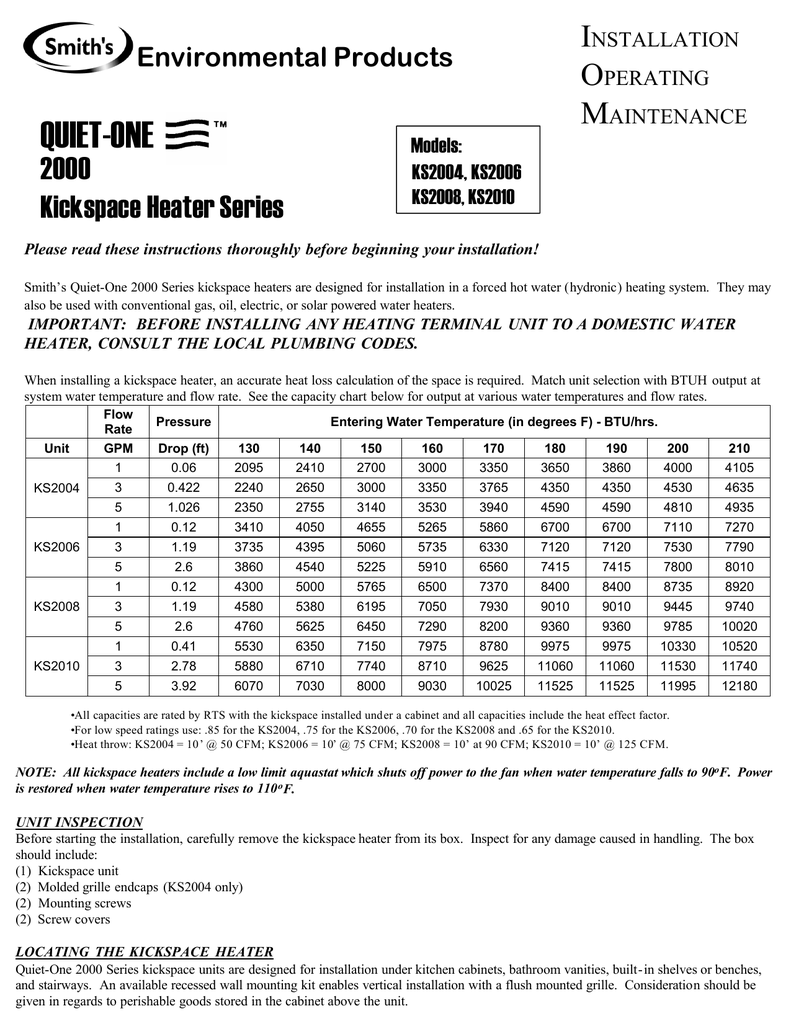
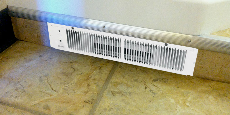
Kickspace heater wiring diagram. Since current drain is very small wiring codes for short circuit protection only will apply. Read and save these instructions voltswattsamps btu hr 2401500 6 35120 2081125 5 43840 120 1500 12 55120 120 750 6 3 2560 planning this heater is designed for installation in an enclosed space such as under a counter or kickspace to provide warm gentle heat at the floor level. 15 mm compression electrical supply. Refer to diagram below for complete wiring instructions.
Power is restored when water temperature rises to 110of. Wiring diagram a wiring diagram b electrical connections caution. 20 bar maximum working pressure. This t stat will only operate the kickspace unit.
For supply connections use wires suitable for at least 194 f 90 c. Kickspace heater page 1 factory wired 240 208 v a c. 220 240 v 50 hz 11. Minutes after the circulator shuts off see diagram 1.
A shaded pole motor is used to drive the kickspace blower on 115 120 v. 10 bar water connections. Wiring diagrams kickspace 500 and 600 standard wiring diagram kickspace 600 12v standard wiring diagram colour code. If the circuit or system circulator is not running the kickspace heater will not operate.
Adding a line voltage type room thermostat will permit the setting of a maximum room temperature see diagram 2.

Wiring Thermostat For Kickspace Heater
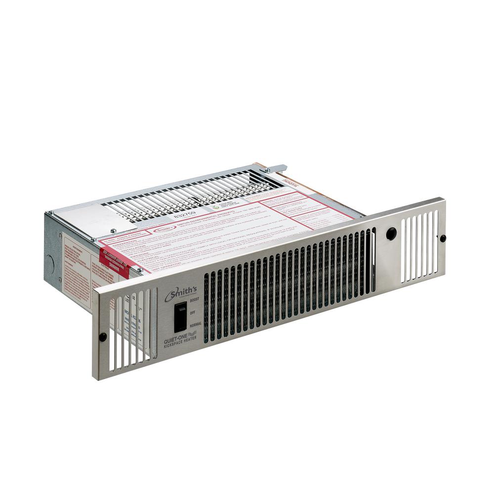
Quiet One 2000 Series 7 100 Btu Hydronic Kickspace Heater In

Toe Kick Heater Installation Piping Layout Question
5 Best Toe Kick Heaters Reviews Of 2019 Bestadvisor Com

Radiators And Convectors Piping Examples Myson Radiators Toe Kick

Myson Kickspace 600 Manuals Manualslib

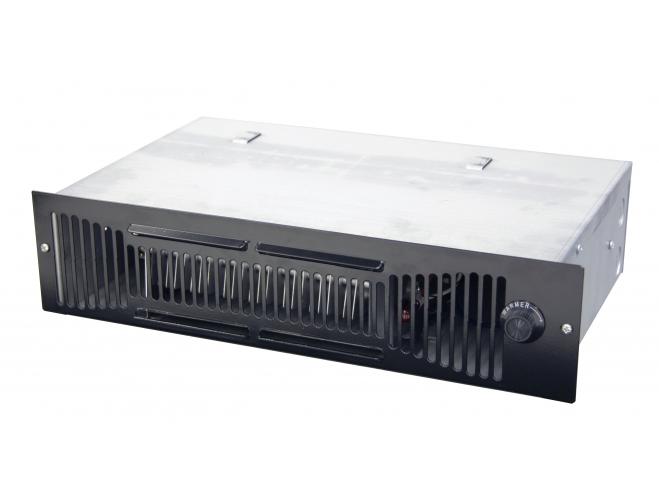
Broan 1 500 Watt Kick Space Heater With Built In Thermostat 112

Turbonics

Toe Kick Heater Confusion 240 Or 120 Doityourself Com Community
Qts Series Toe Space Fan Forced Heater Marley Engineered Products
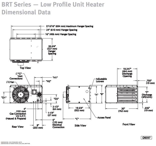
Beaconmorris Beacon Morris Brt Gas Fired Unit Heater 30 120 Mbh

Whispa Iii Hydronic Kickspace Heater 5000 Btu White Tri Level

Quiet One 2000 Series 4 000 Btu Hydronic Kickspace Heater In
